Beginning
Much information about couplers are found here, but I just had to show you this extreme construction!
Since I have worked professionally with radio and TV transmitters for many years I thought that this was something I just had to have... When a large combiner should be exchanged at one of my employers transmitter-sights I just had to put my hands on this coupler.
At these transmitter-sights several transmitters are connected to the same antenna, each transmitter on its own UHF frequency. All combiners are channel-dependent and one combiner is needed for each channel that is transmitted. Every combiner has one broadband input and a narrowband input. The output is always broadband, feeding the next combiner...
Jigsawing and mechanics
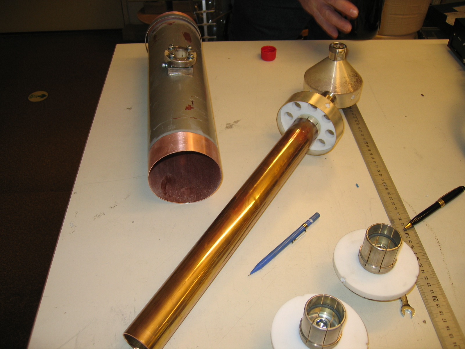
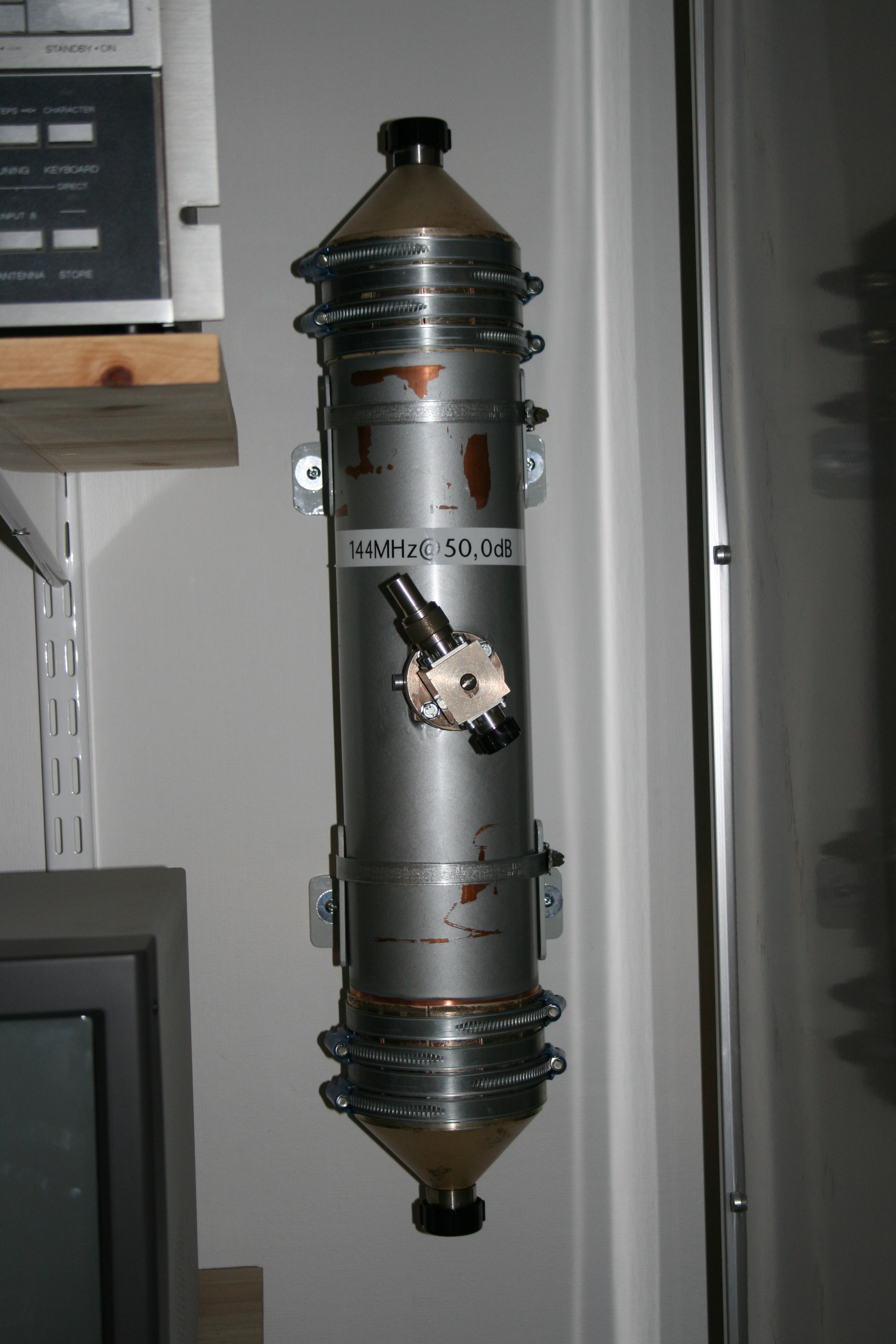
The tube with the coupler is made of copper. The inner-diameter of the outer tube is 98mm and this type of feeder is normally called a ōRL98ö. From the beginning this tube was about a metre long and quite heavy. Robert at work convinced me to cut it down to about half a metre and the pictures are from this jigsaw cutting.
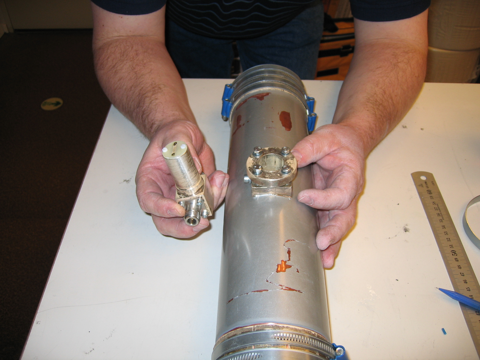
The thinner tube is the inner-tube of the coax. It's held in place by one white teflon-ring in each end. To be able to connect my transmitter to this coupler I must leave the RL98 to an ordinary 7/16-connector. That's made with the conical parts, one in each end of the tube. You can compare it to a BNC to N adaptor, but this is much much bigger!
The coupling factor is adjusted by pushing the sensor into the tube. The distance between the sensor and the inner-tube gives the coupling factor, see picture, exactly the same way as in a Bird-instrument. The big difference is that this coupler will be rock solid and the power-measurement of the coupled output is made with a much higher accuracy.
Measurements
It's no point having this type of coupler if you can't adjust and calibrate it! Since it was hard getting less than 50dB coupling I decided to go for this. It's a little high for reflection-measurements since a 60dBm output and a 30dB returnloss would give you -20dBm on the reflected coupler port. This could be hard to measure, but maybe I just have to buy a new and more sensitive sensor to my power-meter...
Attenuation
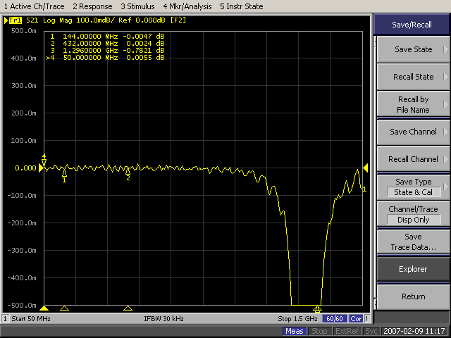
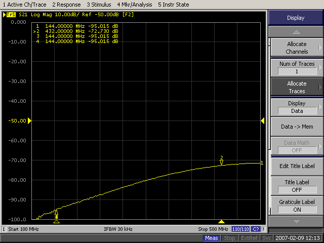
Since the RL98 is made for quite some powerlevels I have never been worried about the attenuation, but I decided to measure it. This first measurement show the attenuation with a double 7/16-female connector. (I had to do this way since I had no calibration-normals for 7/16-connectors.) The attenuation is 0.005dB. The next measurement show the attenuation with the coupler and it's 0.01dB. This means that the total attenuation of the coupler is in the neighbourhood of 0.005dB at 144MHz. You can also clearly see that the measurement show that the coupler can be used up to 23cm but NOT higher! The dimension of the tube is so large it'll act as a waveguide.
Coupling factor adjustments
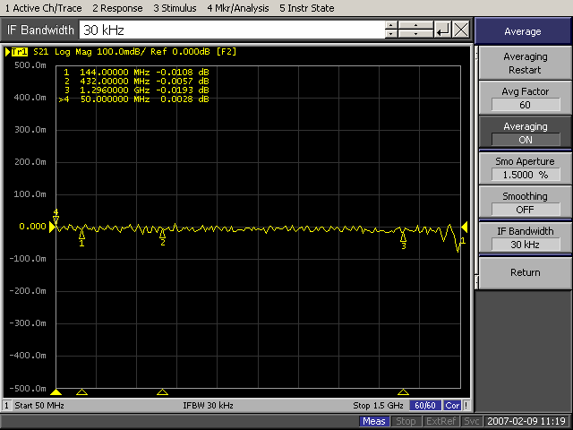
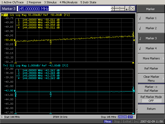
I began to adjust the sensor to about 50dB coupling-factor. After this I reconnect the network analyser to measure the other way to optimize the isolation. The isolation is optimized by rotating the sensor.
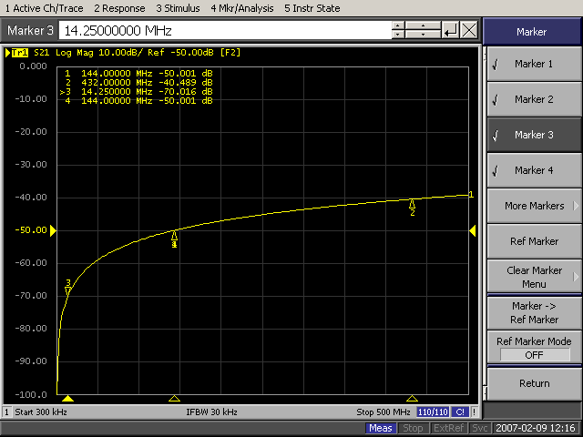
This picture show the result of the coupler adjustment. This picture show the 2m band. The resulting isolation is shown here. The real isolation is 95-50=45dB, and it should be possible to get a little more but I thought that this would be enough...
The coupling naturally decreases with frequency. The decrease is 6dB per octave. You can easily see this if you look at this measurement and look at 14 and 144MHz, ie a difference by 10 times gives 20dB decrease in coupling. 432MHz is three times higher than 144 and 20*log(432/144) = 9.54dB, according to the measurement 9.51dB. (Nice to know that maths work today too...)
Mounting
I decided to mount the coupler on the wall over my desk. In this way it's easy to connect the TX-feeder when it comes down from the ceiling and the amplifier from the 19-inch rack at the right on this picture. On the left I have a power-meter to measure the output or reflected power.