

Background
The biastee is used whenever there is need for several signals on one coaxial cable. Most often only DC-current is fed via the biastee into the coaxial cable but similar constructions could easily be used to let the coaxial-cable carry several different signals. In this way it is possible to feed a tower-mounted transverter with only one coaxial cable.
I have heard that some people believe that feeding a tower-mounted pre-amplifier must be made via a separate cable for the DC-current. This could be true if the DC-current is not “clean”, ie filtered. All signals coming from the power supply will get into the coax and if the power-supply has any spurs or noise near the used RF-frequency this will of course destroy the total receiver system. It is though not hard to get proper filtering and I therefore do not think that one should pay to much attention to this.
One existing example is a normal LNB for satellite reception. To the LNB; DC, DiSeq-signals and sometimes 22kHz for control are fed via the coaxial cable. Nobody complains about this…
My first intention was to build this into my FT225 and in this way DC-supply the pre-amplifier. This is not possible if one would use a cavity filter or some other extra filters since there could be a DC path from the center-conductor to ground. It would not be practical when working without the pre-amplifier and a folded dipole or similar!
Construction
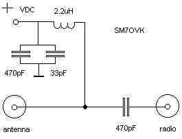
The construction is not critical. The idea is to have a 50ohm line and via a simple LP-filter feed the DC-current into the coax. The LP-filter let DC-current trough but stops the RF-signal. In this way the RF-signal can not get from the coaxial cable to the power-supply.
I made this LP-filter with a small inductor of 2.2uH and some capacitors to ground. It is good to use at least one “large” and one smaller capacitor since they will be “active” on different frequencies. I used a 33pF in parallel with a 470pF, values are not critical. The intention is to get a good broadband RF-grounding of the DC-port. If not, the cable to the power supply could act as an antenna.
Most often the two coaxial ports of the biastee are DC-isolated. This isolation is made with a serial capacitor. This capacitor must be “large” and therefore have low impedance at the used RF-frequency. I use a “SilverMica” found in an old mobile-phone. The value is not critical and I used 470pF.
I recommend the use of a “SilverMica”, or similar type, since these capacitors can handle some power, at least 25W without any problems.
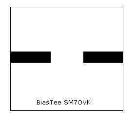
I used a PCB made in glassfibre and it has an epsilon of about 4 and this gives us a width of about 2.5mm. The layout with the “microstrip” is seen here and as you can see it's rather simple. Backside of PCB must be filled with copper.
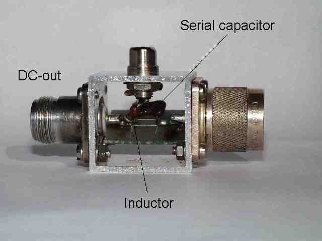
Mechanics
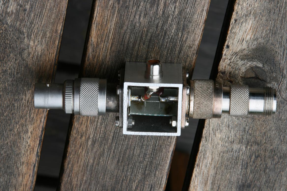
I made the housing with a piece of aluminium profile. The profile measures 30x30x2mm. I cut the profile in a length of about 26mm since the connectors are 1”x1”, ie 25.4x25.4mm. If you need “top and bottom” on the box, do this with some aluminium plates 1-2mm thick. Use small screws as M2 or M2.5. (The design is very similar to how Mini-Circuits build their modules, but I don’t use any top or bottom ie two sides are open.)
The coaxial connectors used are N. I use one male and one female. Take a look at your feeder-system and you will find the best solution for your system, if you have a lot of cables it might be a better idea to have two N females.
I have not used the connector-type with only one mounting-hole since the four screws will secure the connector and it’s a lot easier to connect the ground with these screws.
The DC-port is a RCA-connector but could be a isolated 4mm connector.
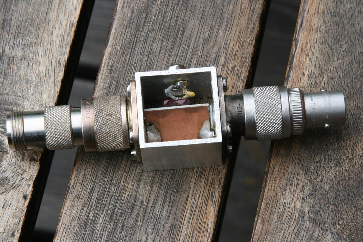
I cut the “microstrip” with a sharp knife, (the opposite side of the PCB should be totally covered by copper). When soldering do not forget to connect the earthside of the pcb to ground! This is made with a small wire, or similar, one on each end of the pcb – close to the connectors. Connect the wire to earth with the help of the connector mounting screws, at least one wire to each connector. Keep the wires short!
More pictures are seen here and here. The white marks are from when the copper was cut with a sharp scalpel. I cut the traces and peel the copper off with the scalpel. You could of course etch the pcb also but this was made very fast and just to clean up everything after etching takes more time than making this pcb.
Performance
The biastee was measured with a network-analyser from Rhode & Schwarz.
The attenuation at 144MHz is less than 0.1dB and the return loss is at least 30dB!
“The other end”
The other end of the cable must of course have the same components, ie one have to put a similar LP-filter inside the pre-amplifier.
Using N-connector or similar high quality connector will also result in a waterproof way of DC-supply the pre-amplifier, if the connector is mounted properly!
NB
It is not nessecary to use the biastee as a biastee, it can also double-work as a DC-block. Sometimes one has outputs or, more often, inputs where you just do not want any DC-voltages. It could be a spectrum-analyzer that can not handle DC-levels above 0V, ie zero volts, and most spectrum-analyzers don’t if they are made for microwaves.