Foreword
Bird instruments for power measurements are put in a special category by some radio-amateurs. These instruments are a rugged construction and made with good quality. They are also OK if you are measuring “simple” modulated signals, but not very accurate if one compare with digital power-meters from Rohde&Schwarz, Agilent (former Hewlett-Packard), Boonton or Gigatronics, (mentioned here in no particular order).
You will never get the same accuracy with a Bird power-meter compared to a “real” power-meter and a calibrated directional coupler. (The biggest difference is if you measure a digitally modulated signal.)
The problem for most radio-amateurs is the price of the Bird instrument or any of the above mentioned instruments. Most amateurs can’t afford to buy a new Bird43 and the problem grows when you have to buy a couple of probes.
What happens inside the Bird instrument?
The key component of the Bird43 is the coupler. A 10cm feedline equipped with a hole where it’s possible to put a special probe. (Bird calls these probes plug-in elements.)
The probe determine the frequency- and power-range of the instrument.
The probe consists basically of a diode. A very small portion of the power through the feedline couples into this diode. The output from the probe is a DC-current. This DC-current is higher with higher power through the feedline.
Here comes the smart part; the maximum current is always 30uA, (according to the meter).
This brief and important message tells us that the manufacturer somehow regulates the current output from the probe and in this way one can use 10W, 100W or whatever-probe and still get 30uA as a maximum current.
The explanation is simple; the coupling-factor between the feed-line and the probe is decreased, ie the distance is increased, at higher power-levels. This is not a “secret” but very important! This is also useable on other couplers.
A 10W-probe will give 30uA at 10W, in the same way will a 25W-probe generate 30uA at 25W. The difference is the coupling but the similarity is the diode. The diode in a 10W-probe will most certainly be of the same type as in a 25W-probe. This tells us that it’s possible to “attenuate” the current from a 10W-probe and in this way be able to use the same 10W-probe for 25W!
The are two drawbacks, the warranty till not be valid after this modification and the diode, inside the probe, will get a slightly higher voltage.
How this is made in some types of Bird instruments
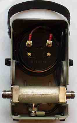
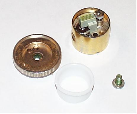
The interior of the Bird model 43 can be viewed here and as another example the Bird model 4304 look like this. Exactly this model is not manufactured any longer, but similar principles are used in the 4304A, 4308, 4410 and so on. What you can’t see on the picture of the Bird43 is that the cable from the probe, a RG58 coax, is twisted several turns around the meter before connected. The length of this coax is about 80cm and this is used to relocate the meter from the coupler, if needed. (The connector from the probe is seen below the coupler.)
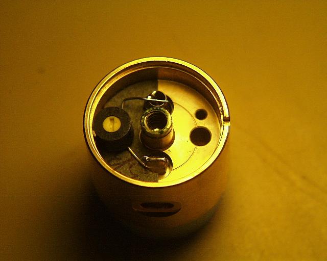
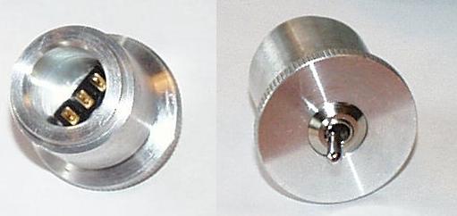
To demystify the probe, after all what you’re pay for is not a solution it’s mechanical precision and reliability, this is how it looks under the cover.
On the first picture a small potentiometer is observed on the left. This potentiometer calibrates the probe, together with the distance between the coupling line and the small coupling loop behind the white Teflon-cover on each probe.
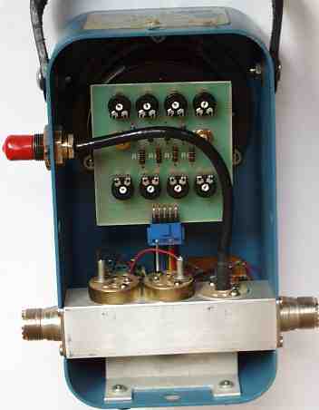
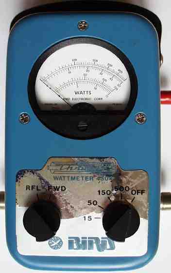
The model 4304 has two switches on the front, one for forward/reflected selection and one for maximum power. The maximum power-level is selected in four steps 15, 50, 150 and 500Watts. When the power-level is selected one also select a “calibration” made with one potentiometer for each power-level, ie a total of eight potentiometers on a pcb mounted on the meter itself, see picture. (As seen on this picture the coupler is not of the same high quality as the model 43! This could be a reason why the instrument is not under production?)
The modification
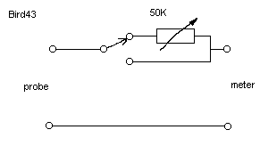
I put an extra switch were it’s possible to change between the standard configuration or to switch in an extra potentiometer. This potentiometer is calibrated once and will later work for all probes. I have chosen to use a multiplication-factor of 2,5 and I do not recommend to use a higher multiplication-factor, since the voltage on the diode could be too high.
I made a small pcb with a 10-turn potentiometer from Bourns and terminals for the switch, the probe and the meter. This pcb is mounted inside the Bird43 and the meter is connected, see diagram.
Practically this is made by changing the meter-connection to the extra small pcb and a short wire connects the meter. The instrument could be slightly more sensitive to RF-energy, after all Bird is using a shielded cable between the probe and instrument, but since the box is made of aluminium I don’t think this is a problem and I have not observed any problems with this. If you want to be on the safe side use short pieces of shielded cable.
Mechanics
Before you decide how you will mount your switch, you must choose a switch. The only important thing about this is that you must find a high quality switch and the most important factor is how many operations this switch is made for. Remember, this switch will be used many times!
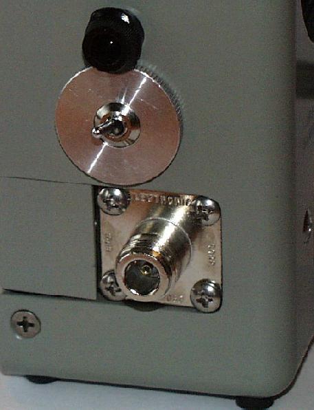
First I decided to use one of the side-holes for the switch. I made a circular plate were the switch is mounted. On the rear of this disc the pcb is held by the switch. A short tube, covers and protect the switch and pcb. The outer diameter of this tube is about the same as the hole-diameter, 26.5mm.
Another and much better way to do this in a very nice way is to use the dust-probe, delivered with each instrument. With a hole drilled for the switch, (my good friend Leif helped me with this nice piece of work!). A tip is to wind some tape around the probe before entered the Bird43, in this way the probe will be very firmly mounted.
It’s an advantage if the switch-arm is short and checked before each operation! Do not flip the switch with power through the instrument!
Calibration
Connect the transmitter via the Bird43 to a good dummyload. I used a 10W probe and transmitted 10W.
Check the output power with the 10W probe and no potentiometer connected. Flip the switch to connect the potentiometer in series with the meter. Adjust until 10W can be read, ie not on the same scale as without the potentiometer!
Now the potentiometer is calibrated. Increase the output-power to 25W and check the readout. If possible, use a 25W probe to control the output-power.
Conclusion and result
With a 10W probe and this modification I measured a 18,5W carrier from my FT225RD. With a 25W probe and without the potentiometer connected I measured 19,5W.
The accuracy of the Bird43 is plus/minus 5% of full scale. With a 25W probe the error could be up to 1,25W, plus/minus. The measured difference of 1W in the example above is therefore what could be expected with this type of instrument.
Here is finally the modified dust-probe mounted on a Bird instrument.
Final
All material on these pages is used on Your own risk! I can’t be held responsible for your mistakes. I have tested this modification on my Bird43 and it works great! I also want to point out that you can’t safely use power-levels higher than the coupler and coaxial-connectors are able to handle. Bird-corporation specifies Bird43 at 1000W maximum on VHF/UHF and 10kW on HF. The instrument will not change this specification if you change the connector from N to 7/16, the coupler will still be the power-limiting component!
Since I now and then see advertisements where hams try to sell probes claiming powerlevels much higher than the instrument specifications, I would like to point out that the Bird43 is only made for probes from Bird-tables 1, 2, 3, 4, 6, and 14 ie not table 5! (Table 5 contain probes with powerlevels 500-10000W 25-1260MHz with several different probes.) There are also probes around made for the larger couplers and these are marked with let say 5kW and 50-125MHz 5KB1, but these are not made for the Bird43!
(The 5KB1-probe is made for 100uA-instruments, Bird43 has a 30uA-meter!)
If you are using very high power-levels it might be a good idea to buy, or build, a high power coupler. This coupler could then use the same principle as described above or even better connect the coupled outputs to a “real” power-meter. If the coupler is calibrated you will have much more accurate measurements, remember the Bird-accuracy is 5%. A coupler together with a mW-meter, both calibrated, could have an accuracy of much less than a tenth of a dB.